Dynamics and Control II
Solution of Problem Set 5
Assigned: March 7, 2008 Due: March 14, 2008
Problem1:
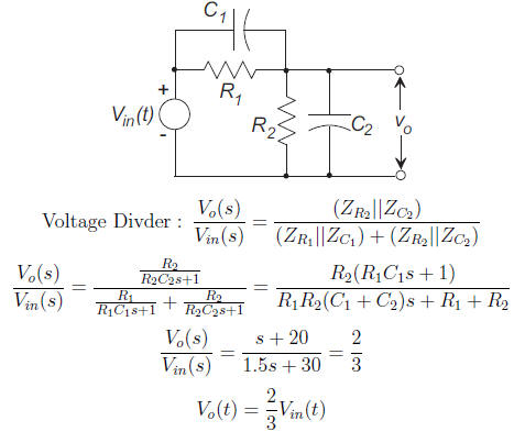
(a)
Use the voltage division rule :
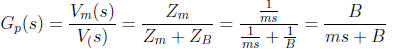
(b)
Problem2: (ModifiedfromProblemSet4.)
All the calculations of this problem are carried out by attached MATLAB code.
(a)
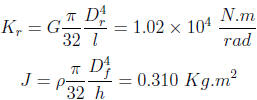
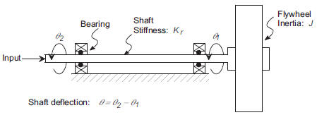
In the above relations h is the flywheel thickness and Df
= .3 m and Dr = .05 m
are the flywheel/shaft diameters. The J of shaft can be similarly computed and
found
to be equal to 0.024 Kg.m2. The shaft inertia is an order of
magnitude smaller than
flywheel inertia and for our simple model we ignore it.
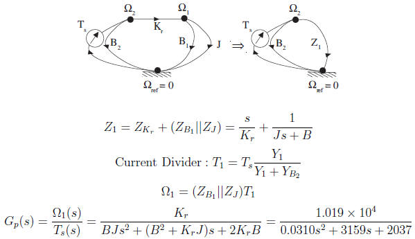
(b) Assume that B1 = B2 = B
anddefine  =Ω1 and
 =Ω2:
=Ω2:
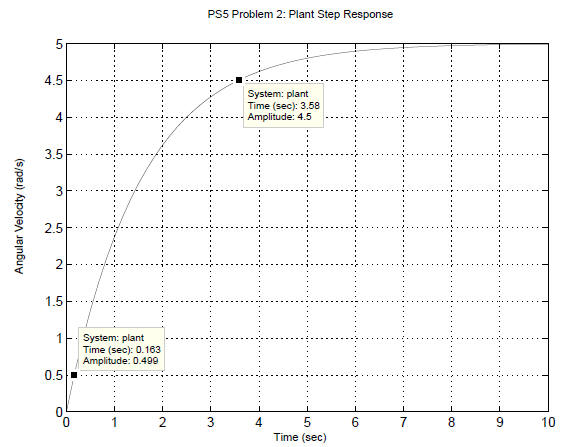
(c) For the open loop system the steady state output for a
unit step is equal to G(0) =
 From this plot the “rise-time” is estimated
to be equal to3.58−.163 =3.427
From this plot the “rise-time” is estimated
to be equal to3.58−.163 =3.427
sec.
(d) From the plot the “rise-time” is estimated to be equal to .0761−.00328 =0.0728 sec.
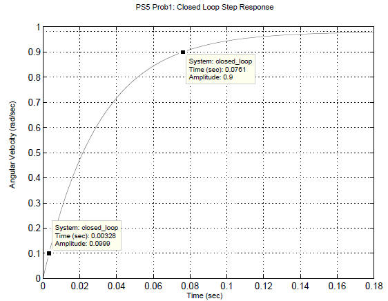
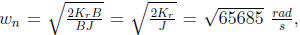
(e) The proportional control has increased the rise time
substantially. The rise time can be
related to ωn which can be computed from the transfer function:
Closed Loop :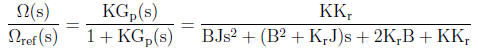
Closed Loop: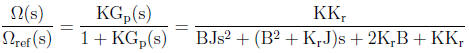
For the open loop system
 while for the closed
 and hence K
has a huge effect on the rise time.
MATLAB m −file :
clear all,clc,close all
% Symbolic Transfer Function
syms B Kr J s Ts
Z1=s/Kr+(1/(J*s+B));Y1=1/Z1;YB=B;
T1=simple(Ts*Y1/(Y1+YB))
Omega_1=simple(T1*1/(J*s+B))
clear all
% Compute the value of J
d = 0.3; h = 0.05; rho = (7.8*1e-3)/1e-6; J = pi/32*rho*h*d^4
% Compute the value of K
G = 83e9; l = 5; D = 5e-2; Kr = pi*G*D^4/32/l
% B=B1=B2
B=0.1;
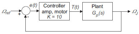
% From our analysis the plant transfer function Gp(s)= WJ(s)/T(s) is:
% Gp(s) = Kr/(B*J*s^2 + (Kr*J + B^2)s +2*Kr*B)
% Display the undamped natural freqency
wn = sqrt(Kr/J)
plant =tf([Kr],[B*J (Kr*J+B^2) 2*Kr*B])
figure(1)
step(plant);
ylabel(’Angular Velocity (rad/s)’)
title(’PS5 Problem 2: Plant Step Response’)
set( gcf ,’color’,’w’),set(gca,’fontsize’,12)
box on, grid on,set(gcf,’position’,[100,100,600,400])
% Form closed loop system -controller, etc, gain is 10:
closed_loop = feedback(10*plant,1)
figure(2)
step(closed_loop)
ylabel(’Angular Velocity (rad/sec)’)
title(’PS5 Prob1: Closed Loop Step Response’)
set(gcf,’color’,’w’),set(gca,’fontsize’,12)
box on, grid on,set(gcf,’position’,[100,100,600,400])
Problem3:
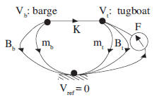
A linear graph model of the system is shown above and then
ode equations are derived below.
The two masses represent inertial forces of the tugboat and the barge. Since
usually mt is
very smaller than mb, we can ignore the tugboat mass to further
simplify the model. The K
stiffness represents the cable elasticity and Bt and Bb represent water drags on
tugboat and
barge. This system has three independent energy storage elements and transfer
functions
like  are third orders. The attached
MATLAB code computes the Vtand Vb and
are third orders. The attached
MATLAB code computes the Vtand Vb and
proves that our transfer functions would be third orders.
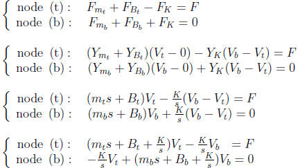
MATLAB Command− line :
>> syms mt mb Bt Bb K F Vt Vb s real >> eq1=(mt*s^2+Bt*s+K)*Vt-K*Vb-F*s;
>> eq2=(mb*s^2+Bb*s+K)*Vb-K*Vt;
>> [Vb,Vt]= solve (eq1,eq2,Vb,Vt)
Vb =
K*F/(mt*mb*s^3+s^2*mt*Bb+s*Bt*Bb+s*mt*K+s*K*mb+s^2*Bt*mb+Bt*K+K*Bb)
Vt =
(mb*s^2+Bb*s+K)*F/(mt*mb*s^3+s^2*mt*Bb+s*Bt*Bb+s*mt*K+s*K*mb+s^2*Bt*mb+Bt*K+K*Bb)
Problem4:
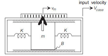
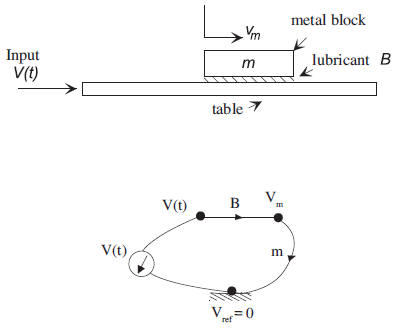
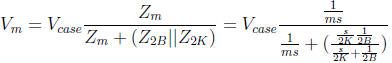
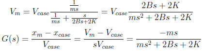
(a) Vm is defined as the absolute velocity:
(b) There are two independent energy storage elements: one
is the mass inertia (requiring
to know Vm) and the other is the spring (requiring to know xm
- xcase). The two
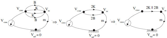
springs act in parallel and are dependent.
(c) The mesh equation for a single loop would be the same as the voltage
division rule :
Voltage Divider:
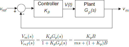
Problem5:
We have two energy storage elements, but in general
the order of system should be one. This
means that our energy storage elements are dependent and that’s true be cause if
we know the
voltage of one capacitor, the voltage of the other capacitor is know as well
Furthermore, for this particular given values of parameters the order of system
is zero due
to a zero-pole cancellation.
| Prev | Next |